
Two phase separator for gas and liquid separation
A two phase separator separates free gas from the combined liquid phase of a wellstream. The inlet device reduces momentum; gas disengages into the vapour space and passes through a mist extraction stage before leaving through the gas outlet. Liquid collects below and is discharged under level control. The vessel is specified for the actual gas and liquid rates, fluid properties and operating envelope.
MechOilfield Equipment Pvt. Ltd. develops skid mounted and, where required, trailer mounted separator packages for well testing, production and upstream process applications in India. A technical offer can include the pressure vessel, internals, piping, valves, instruments, structural support, controls, inspection and documentation. Final equipment scope follows the approved datasheet and P&ID.
Engineered around the wellstream
Gas handling and liquid retention are evaluated together. The design review considers gas velocity, entrained droplets, liquid residence time, slugging, foaming, sand, erosion and the required carryover limit. A horizontal vessel may suit higher liquid rates and hold-up needs; a vertical vessel may suit a different flow envelope or plot constraint. The final orientation is selected after process review.
Data needed for sizing
- Minimum, normal and maximum gas and liquid flow rates, including turndown and slug conditions
- Operating and design pressure and temperature; gas composition and liquid density and viscosity
- H₂S, CO₂, sand, foaming tendency, corrosion allowance and separation targets
- Applicable design code, site conditions, transport limits and required documentation
Engineering deliverables
- Process and mechanical datasheets, general arrangement and nozzle schedule
- P&ID, control philosophy and instrument and valve list as agreed
- Mechanical design calculations, fabrication drawings and lifting or mounting details
- Inspection and test plan with project specific hold points
Nominal vessel size, wall thickness, pressure rating and flow capacity cannot be responsibly stated from diameter or pressure alone. They are confirmed after the design basis and applicable code requirements are approved.
Internals and mounting engineered for the duty
Depending on duty, the vessel can be specified with an inlet diverter, calming arrangement, mist eliminator, vortex breaker, anti-foam provision and sand handling connections. Internals are selected for the separation target and maintainability.
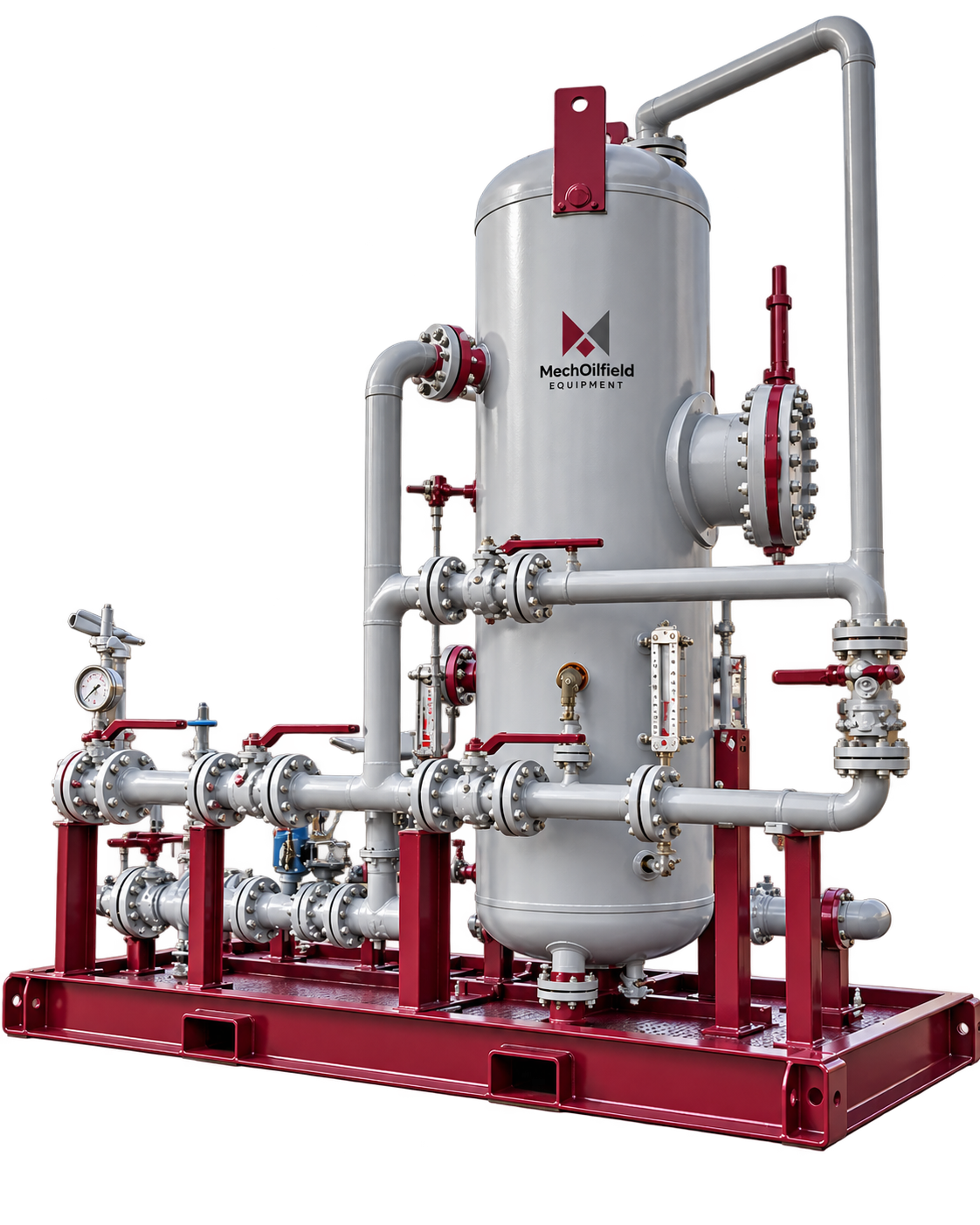
Skid-mounted two-phase separator
Structural support, lifting points, centre of gravity, access and piping tie-ins are reviewed for the specified site and operating loads. Tie-downs, forklift pockets, protective frame and coating can be scoped where required.
DNV 2.7-3 offshore skid option. For portable offshore units, the skid and protective frame can be engineered to DNV-ST-E273 (2.7-3) when specified. Inspection, testing and unit-specific certification are confirmed in the project offer.
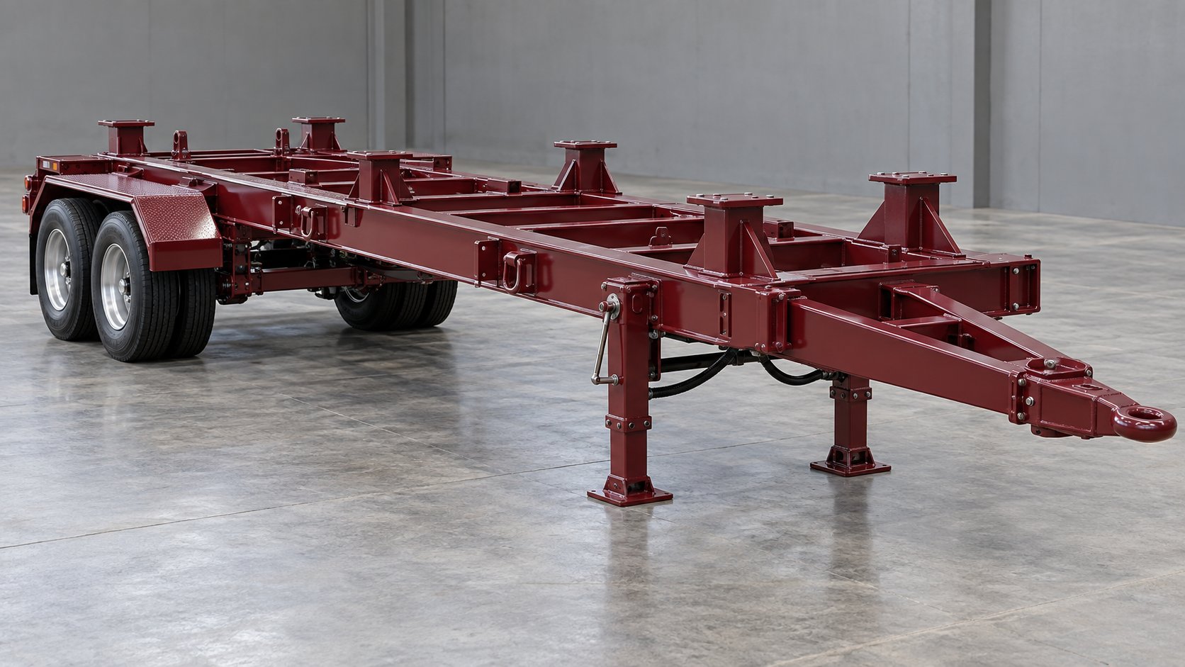
Trailer chassis option
Trailer integration considers gross transport mass, axle loads, centre of gravity, route height and width, coupling, brakes, suspension and stabilising supports. Transport restraints and the operating setup are reviewed separately.
Trailer chassis shown without equipment. Final separator mounting, chassis dimensions, transport envelope and road approvals depend on the project and destination.
Defined line by line in the approved P&ID
The following is a typical scope discussion, not a fixed bill of materials. Connection sizes, pressure classes, valve quantities and makes are selected for the project.
| Line / connection | Potential package items | Control and measurement |
|---|---|---|
| Wellstream inlet | Isolation, inlet connection, drain and inlet device | Pressure and temperature indication or transmitters as specified |
| Gas outlet | Isolation, pressure control, relief and optional gas metering | Pressure control valve, pressure transmitter, PSV and meter as specified |
| Liquid outlet | Isolation, liquid level control, sampling and optional metering | Level transmitter or controller, level control valve and flowmeter as specified |
| Vent and drain | Depressurising, closed drain and maintenance connections | Arrangement follows the approved safety philosophy |
Materials, sour-service requirements, relief sizing and instrument selection are reviewed against the fluid and project specification. An emergency shutdown system or control panel can be considered as part of a wider well testing package.
Inspection planned from the design basis
The pressure vessel may be designed to ASME Section VIII Division 1 when specified. Welding procedures and personnel qualifications, material traceability, NDT extent, heat treatment, hydrostatic test and third-party inspection are established in the approved code and inspection plan. U-stamp supply is discussed only where the agreed manufacturing and inspection route supports it; certification is confirmed in the technical offer.
Deliverables can include material test certificates, weld and NDT records, pressure test reports, calibration records, approved drawings and a manufacturing data book. Surface preparation and coating are specified for the environment and agreed paint system, with dry film thickness and inspection requirements stated in the offer.
Two phase separator questions
When should a three phase separator be selected instead?
A two phase unit separates gas from a combined liquid stream. If oil and water need separate controlled outlets or individual measurement, review a three phase separator and provide the oil and water rates and separation target.
Can the separator be supplied as part of a 5K or 10K well testing spread?
Yes, the required separator duty can be evaluated within a 5K or 10K well testing package. The package pressure class does not by itself set the separator vessel design pressure; the pressure boundary and process arrangement are defined in the project P&ID.
What should I send for a technical quotation?
Share the process datasheet or minimum and maximum gas and liquid rates, pressures, temperatures, fluid properties, sour or sand content, required mounting, code, inspection scope and delivery location. We will review the basis and reply with a project specific technical offer.
Two phase separator or three phase separator?
A two phase separator separates free gas from a combined liquid stream. A three phase separator adds controlled separation of oil and water into distinct liquid outlets. The choice depends on whether separate oil and water measurement or handling is required, the fluid properties and the operating envelope. A two phase unit should not be specified as an oil-water separator when the process needs three distinct outlet phases.
Two phase separator design and manufacturing
MechOilfield develops two phase separator equipment around the project datasheet. Horizontal or vertical arrangement, inlet devices, mist extraction, retention volume, nozzle locations and control interfaces are reviewed against the specified gas and liquid duties. For a technical quotation, provide normal, minimum and maximum flow rates, operating and design conditions, fluid composition, separation targets and site or transport constraints. The offer defines the applicable design code, inspection scope and documentation.
Need design services only?
Explore our design and engineering services for calculations, modelling and fabrication drawings, or contact our team with your equipment scope.