Three phase separator manufacturer in India
A three phase separator divides a mixed wellstream into gas, oil and water. Inlet momentum is reduced, gas disengages in the upper vessel space, and the two liquid phases settle according to their density difference. Mist extraction, level control and interface control support the specified separation performance.
MechOilfield Equipment Pvt. Ltd. engineers and manufactures three phase separator packages in India for surface well testing and oil and gas production. Each package is developed from the client’s process data and project specification. The offer can cover the pressure vessel, internals, skid or trailer, interconnecting piping, valves, instrumentation, controls, testing and documentation.
Sizes and pressure classes
Indicative configurations for initial discussion. Capacity depends on fluid properties, gas volume, operating conditions, required separation quality and internals. Dimensions, wall thickness and rating require project specific engineering verification.
| Design pressure | Nominal vessel size | Indicative liquid capacity |
|---|---|---|
| 800 psig | 34 in × 8 ft | 3,500 BPD |
| 1,440 psig | 30 in × 10 ft | 3,500 BPD |
| 1,440 psig | 42 in × 10 ft | 10,000 BPD |
| 1,440 psig | 42 in × 15 ft | 12,000 BPD |
| 1,440 psig | 48 in × 10 ft | 13,000 BPD |
| 1,440 psig | 48 in × 12 ft | 19,000 BPD |
| 1,440 psig | 48 in × 15 ft | 19,000 BPD |
| 2,160 psig | 24 in × 10 ft | 1,000 BPD |
| 2,160 psig | 42 in × 15 ft | 12,000 BPD |
Other sizes, pressure ratings and capacities can be evaluated against client requirements. Vessel thickness is calculated for the approved design basis; it cannot be inferred from pressure and diameter alone.
From process data to a buildable package.
Data we review
- Oil, gas and water flow rates and turndown
- Operating and design pressure and temperature
- Oil API gravity, density, viscosity and gas composition
- Gas–oil ratio, H₂S, CO₂, sand and solids content
- Retention time, separation targets and code requirements
Engineering we define
- Vessel geometry, liquid hold-up and gas disengagement area
- Inlet device, mist extraction and interface arrangement
- Nozzle sizes, reinforcements and mechanical design
- Level, pressure and safety control philosophy
- General arrangement, P&ID and project documentation
Pressure vessel design can be specified to ASME Section VIII Division 1. U-stamp supply is an option only where the approved manufacturing and inspection route supports it; availability is confirmed in the offer.
Lines, controls and instrument options.
The actual line sizes, valve quantities, pressure classes and instruments are defined in the approved P&ID and bill of materials. Typical scope can include:
| Process line | Typical arrangement | Control / measurement |
|---|---|---|
| Inlet | Inlet isolation, pressure indication and distribution device | Pressure and temperature measurement as specified |
| Gas outlet | Isolation, pressure control and safety protection | PCV, PSV, pressure transmitter and optional gas metering |
| Oil outlet | Isolation, level control, check and sampling as specified | LCV, level transmitter and optional Coriolis flowmeter |
| Water outlet | Isolation, interface level control and sampling as specified | Interface measurement, LCV and optional flowmeter |
| Drain / vent | Safe depressurising, drains and maintenance connections | Configuration as required by approved P&ID |
Indicative instrument and valve makes
| Item | Available make options for project review |
|---|---|
| Safety relief valves | Farris, LESER, Denovo |
| Control valves | Emerson Fisher, Pneucon, Masoneilan |
| Pressure / level transmitters | Rosemount, Yokogawa, Honeywell; Magnetrol, ABB K-TEK |
| Gauges | Micro, WIKA, Ashcroft |
| Oil / water flowmeters | Micro Motion, Endress+Hauser, KROHNE, Emerson |
| Gas metering | Canalta, Emerson, Daniel |
| Isolation valves and actuators | L&T, Audco, Velan; Bettis, Rotork, Flowserve |
Examples show potential supply options, not endorsements, installed equipment or guaranteed availability. Final selection follows the client approved vendor list and technical specification.
Fabrication with documented checks.
Material & welding
Material certificates and traceability; approved WPS, PQR and welder qualifications to ASME Section IX as applicable.
Inspection & testing
Dimensional and visual checks, required RT / UT / MT / PT, PWHT where required, hydrostatic testing, calibration and loop checks.
Documentation
Project specified inspection records, material records, test certificates, drawings and manufacturing data book.
The inspection and testing plan is set against the applicable code, approved drawings and project requirements.
Skid-mounted or trailer-mounted separator.
Select the arrangement around site access, lifting and transport. The separator vessel, piping and controls are configured to the approved process duty; the supporting structure is engineered for the chosen installation.
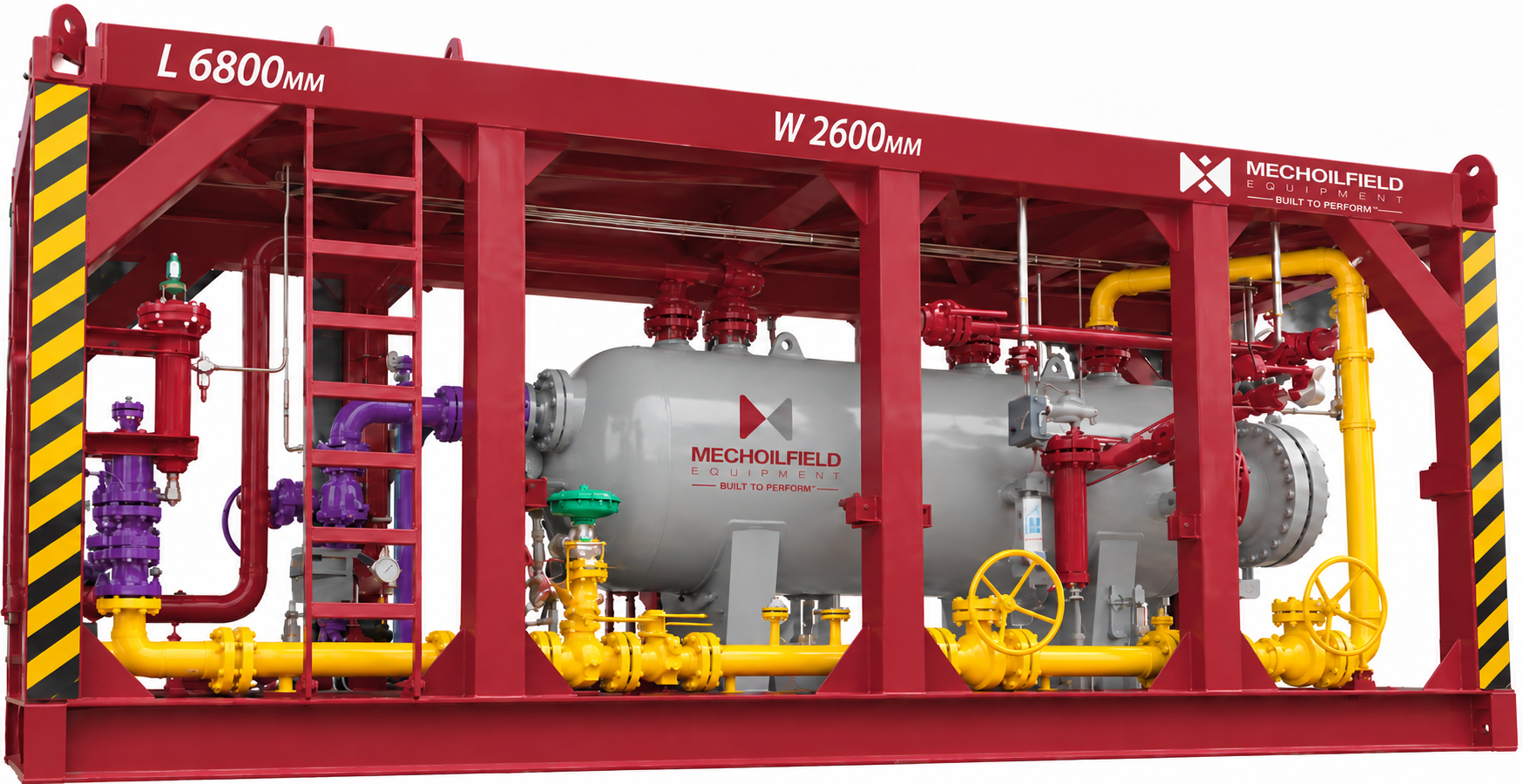
Skid-mounted configuration
A compact package for lifting, placement and connection at the wellsite or processing facility. The frame layout can accommodate vessel supports, piping, access and maintenance clearances.
- Structural load cases, lifting points and centre of gravity reviewed for the specified duty
- Forklift pockets, tie-downs, drip containment and protective crash frame where required
- General arrangement, support calculations, weld inspection and coating scope defined in the offer
DNV 2.7-3 offshore skid option. For portable offshore units, the skid and protective crash frame can be engineered to DNV-ST-E273 (2.7-3) when specified. Inspection, testing and unit-specific certification are confirmed in the project offer.
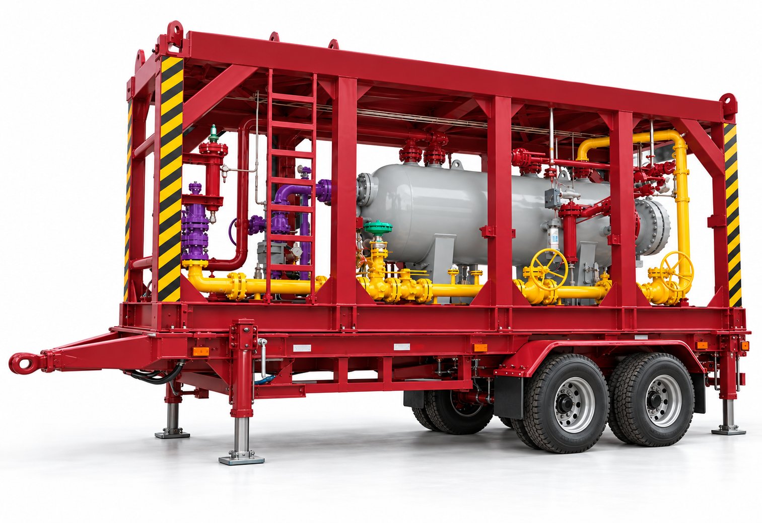
Trailer-mounted configuration
For projects requiring movement between sites, the separator package can be integrated with a road trailer chassis and a stable operating setup.
- Transport mass, axle loads, centre of gravity and route envelope evaluated for the specified location
- Drawbar or coupling, suspension, brakes, tyres and stabilising legs selected to suit the design
- Operating supports, access and piping tie-ins planned separately from transport restraints
Illustrative configuration. Final separator mounting, chassis, transport design and road approvals depend on the project and destination.
Protective coating
Surface preparation and a coating system can be specified for the service environment, for example Sa 2½ blast preparation with zinc-rich epoxy, high-build epoxy and polyurethane topcoat. Typical total dry film thickness of 250–350 μm is confirmed by the approved coating specification.
A 10–15 year or longer coating design life may be targeted for a defined environment and maintenance regime. Service life is not a universal guarantee; the final system and any warranty are agreed in the offer.
Three phase test separators for well testing and production
A test separator separates and measures the gas, oil and water produced by an individual well during a defined test period. Production separators perform separation as part of the ongoing processing system. The operating envelope, metering accuracy, liquid handling and required outlet quality determine the appropriate package.
Separator within a well testing package
The separator works with upstream flow control and downstream liquid handling. Review the complete 5K well testing package or 10K well testing package, together with the choke manifold and surge tank. The separator vessel pressure rating is selected separately from the upstream well-control equipment rating.
Manufacturing and project support
Mechanical design, vessel fabrication, package piping, instrumentation and quality documentation are coordinated around the approved equipment scope. Learn about our manufacturing capabilities and engineering services, or send your separator datasheet for a technical offer.
Three phase separator questions
What is the difference between a two phase and three phase separator?
A two phase separator separates gas from a combined liquid stream. A three phase separator also separates the liquid into oil and water, with dedicated outlets and liquid-interface control. Compare our two phase separator for duties where separate oil and water outlets are not required.
Can a 10K well testing package use a 1,440 psig separator?
Upstream equipment rated at 10,000 psi does not make the entire spread suitable for that pressure. Any lower-rated separator requires an engineered pressure-reduction and overpressure-protection arrangement. Pressure boundaries, operating cases and shutdown requirements are defined in the approved P&ID.
What determines three phase separator capacity?
Capacity depends on gas, oil and water rates at operating conditions, fluid properties, separation targets, vessel geometry and internals. A BPD figure or vessel size alone is insufficient to establish performance.
How is a separator quotation prepared?
Send the fluid rates and properties, operating and design conditions, required outlet quality, metering and control scope, mounting arrangement and delivery destination. The quotation defines vessel and package scope, inspection, documentation, price and delivery against those requirements.